Grit is removed by maintaining a constant upstream velocity of 03 ms 1 fts. Aerated grit chambers are versatile allowing for chemical addition mixing pre-aeration and flocculation.
2
Average flow 60 MLD 0694 m3sec and Peak flow 0694 x 20 1389 m3sec 2.
. Formulation and related design parameters for Venturi flume control are presented in appendix C. Depth 025 05 free board 025 space for grit. GRIT CHAMBER Grit chamber is the second unit operation used in primary treatment of wastewater and it is intended to remove suspended inorganic particles such as sandy and gritty matter from the wastewater.
If you are facing any difficulties with the new site and want to access our old site please go to httpsarchivenptelacin. This is usually limited to. Entry of approx not to exceed 08 m3m3hr with grit chambers under 3 m2 cross section area and 13 m3m3hr with larger grit chambers Grit Amount 4200 m3million m3 water 5200 m3million m3 water Diffuser location located about 045 to 06 m above the normal plane of the bottom.
Velocity is controlled by proportional weirs. Maintenance is significantly reduced. Length width 40 m.
3 Design aerated grit chamber for treatment of sewage with average flow of 60 MLD. Aerobic Secondary Treatment Of Wastewater. L-13 Grit Chamber Environmental Engineering-II 2.
Existing hitherto methods of design of. The average wastewater flow is 05m3sec and the peak flow factor is 27 times of average flow. The assumption is that the horizontal grit chamber that is 135 m in length if the average grit chamber flow is 015 m3s the width of the chamber is 056 m and the horizontal velocity is.
Request PDF Aerated Grit Chambers Hydraulic Design Equation The paper is devoted to the problem of dimensioning of aerated grit chambers. Solution The max flow per channel will be 650003 21666 m3day 025 m3s. Performance of downstream units may be improved by using pre-aeration to reduce septic conditions in incoming wastewater.
Other Primary Treatment Systems. Theoretical length L 92 m provide 25 extra length hence length 115 m. One design option includes a grit auger and a rake that removes and classifies grit from the grit sump.
The design velocity V h is 025 ms. Horizontal Flow Grit Chamber The horizontal flow grit chamber is the oldest type of grit removal system. 2 GRIT CHAMBER DESIGN 369 O o LU CO ce LU.
Example 3 Design a grit removal system consisting of three identical channels for a plant which has a max flow of 65000m3day an average flow of 50000m3day and a minimum flow of 20000m3day. The design of the effluent channel and other structures below the flume must be such that the head loss between the grit chamber and the effluent channel is not less than one-third th e difference in elevations of the upstream crest and flume floor. Aerobic Secondary Treatment Of Wastewater.
All are for civil engg. L 13 grit chamber 1. 2 treatment plant are screening andor grinding grit removal flow measurement flow control and 3 sometimes odor control.
415 Design Discharge Level The water surface elevation in the receiving structure decides the static lift when compared to the suction level. Width 1 m. Consistent removal efficiency over a wide flow range.
Assume SOR 1200 m3 m2day. Raw 4 wastewater contains sticks rocks sand bottles scraps of metal rags and many other similar 5. Design a set of rectangular grit basins with proportional flow weir for a plant which has a peak flow of 80000 m3day max 3flow of 65000 an average flow of 50000 m day and a minimum flow of 20000 m3day.
Grit Chamber Contd Primary Sedimentation Tank. The mechanical design is. Consider the peak factor of 2.
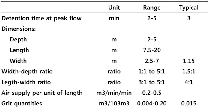
1 Design a bar screen chamber for average sewage flow 20 MLD minimum sewage flow of 12 MLD and maximum flow of 30 MLD. 7 1242 m 3 for each grit chamber To find the dimensions of each grit chamber assume the depth is 3 m Use a width depth ratio of 12-1 W 15 3 45 m Length L Volume WD 1242345 92 m To determine the air supply requirement assume that 03 m 3 m. Wastewater in grit chamber and second showing cross section of grit chamber Example.
Assume manual cleaning and angle of inclination of bars with horizontal as 30o. Average flow 20 MLD 0231 m3Sec Maximum Flow 30 MLD 0347 m3Sec Minimum flow 12 MLD 0139 m3Sec 2. Co or LU b 2 a o z DIAMETER OF PARTICLE d IN CENTIMETERS Fig.
Other Primary Treatment Systems. Design of Grit Chamber -Environment Civ105- 15 - Free download as PDF File pdf Text File txt or read online for free. Aerobic Secondary Treatment Of Wastewater.
Detailed design of Grit Chamber for STP SNO Design parameter Design Value 1 Design flow m3s 0069 2 Width of Grit chamber m 3 3 Depth of Grit chamber m 2 4 Assume Kinematic Viscosity of Effluent m2s O000011 5 Assume Particle Diameter m. As a rule if needed this has to be increased such that the. Min Air required 92 03 276 m 3 min for each grit chamber Total air supply required 2762.
Depth 0973 03 free board 025 space for grit accumulation Say 16 m. 13 Billion views 37 lakhs YouTube subscribers 2300 unique courses available for self study. Solution Average quantity of sewage considering sewage generation 80 of water supply is 135 x 50000 x 08 5400 m3day 00625 m3sec Maximum flow 25 x average flow.
Make the peak depth equal to the width. Volume of grit chamber. Example1 Design a grit chamber for population 50000 with water consumption of 135 LPCD.
However friction losses and free-fall at receiving chamber are to be added to this to get at the design discharge level. Use two tanks calculate the grit chamber volume and grit materials if 005 m 310 m of peak flow is the grit concentration. Design Example of Settling Channel and Control Device.
Figure 2 shows the settling velocity analysis of a sample of grit taken from the Leominster Mass grit chambers which are typical American type chambers. 06 m above the sloping tank bottom. Introduction and Objective Grit removal basins are the sedimentation basins placed in front of the fine screen to remove the inorganic particles having specific gravity of 265 such as sand gravel grit egg shells glass piecesgravel grit egg shells glass pieces metal fragments.
These steps together are referred to as preliminary treatment. This sample was washed to remove putrescibles before the settling. The settling velocity of grit particles in the range of 01 mm and 1 mm can be determined using equation 118 or its approximate empirical form of equation 1110 and these should be used in the design of grit chambers which are designed to remove particles of size 015 mm or 02 mm.
Example Design an aerated Grit Chamber for the treatment of Municipal waste water. Vc 227 cmsec.

What Are Grit Chambers Classification Disposal Of Grit Skimming Tanks Civildigital
2

Detailed Design Of Grit Chamber For Stp Download Table

Pdf Aerated Grit Chambers Hydraulic Design Equation Semantic Scholar
2

Grit Chamber Composition Types Working Principle And Advantages The Constructor
Types Of Grit Chambers Horizontal Flow Aerated Vortex
2
0 comments
Post a Comment